
With the ever-increasing reliance on cell phones in our daily lives, understanding how they work and how to optimize their performance has become essential. One popular topic among cell phone enthusiasts is how to make a GSM data receiver. A GSM data receiver is a device that allows you to intercept and analyze data transmitted over a GSM network. Whether you’re curious about the inner workings of cell phone communications or you have a specific use case in mind, learning how to create your own GSM data receiver can be a fascinating and empowering endeavor. In this article, we will explore the basics of GSM technology, the components and steps involved in building a GSM data receiver, and the potential applications of this device. So, let’s dive in and unlock the secrets of GSM data receivers!
Inside This Article
- Components Needed: GSM module, Antenna, Arduino board, SIM card, Breadboard and jumper wires
- Wiring Connections – Connecting GSM module to Arduino – Connecting antenna to GSM module – Inserting SIM card into GSM module
- Setting up Arduino Code- Downloading and installing necessary libraries- Writing code to initialize GSM module- Configuring GSM module settings
- Testing and Troubleshooting – Uploading code to Arduino, Sending and receiving data with GSM module, Troubleshooting common issues
- Conclusion
- FAQs
Components Needed: GSM module, Antenna, Arduino board, SIM card, Breadboard and jumper wires
When it comes to building a GSM data receiver, there are a few key components that you will need. These components are essential for creating a functional and reliable device. Let’s take a closer look at each one:
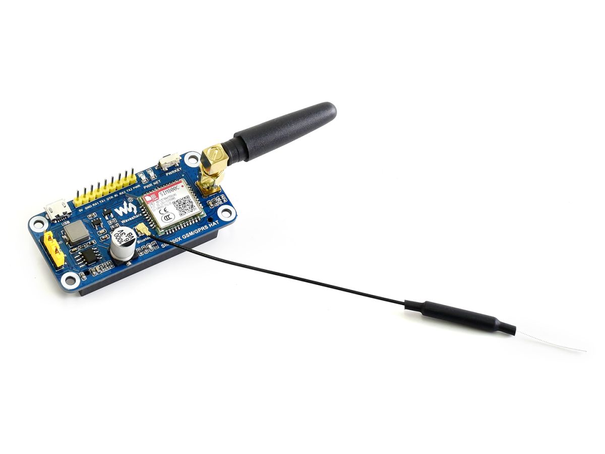
GSM module: One of the central components of a GSM data receiver is the GSM module. This module is responsible for establishing the communication between the device and the cellular network. It allows you to send and receive data using the Global System for Mobile Communications (GSM) technology.
Antenna: To ensure a strong and stable signal reception, you will need an antenna. The antenna is connected to the GSM module and is responsible for transmitting and receiving signals to and from the cellular network. A high-performing antenna is crucial for optimal data transmission and reception.
Arduino board: An Arduino board is used as the main control unit for the GSM data receiver. It provides the necessary processing power and interfaces to connect and control other components. Arduino boards are popular among electronics enthusiasts due to their versatility and ease of use.
SIM card: To connect to the cellular network, you will need a SIM card. The SIM card contains your subscription information and allows the GSM module to authenticate and communicate with the network. Make sure that your SIM card is compatible with the network frequencies supported by your GSM module.
Breadboard and jumper wires: To establish the necessary electrical connections between the components, you will need a breadboard and jumper wires. The breadboard provides a convenient platform to connect and prototype your circuit. Jumper wires are used to make the connections between the GSM module, Arduino board, antenna, and other components.
By gathering these components, you will have everything you need to start building your GSM data receiver. Each component plays a crucial role in the overall functionality and performance of the device. Now let’s move on to the next step, which is wiring the connections.
Wiring Connections – Connecting GSM module to Arduino – Connecting antenna to GSM module – Inserting SIM card into GSM module
When it comes to building a GSM data receiver, the wiring connections are crucial. By properly connecting the GSM module to the Arduino, connecting the antenna to the GSM module, and inserting the SIM card, you can ensure smooth communication and data transfer. Let’s take a closer look at each of these steps:
Connecting GSM module to Arduino: To establish a connection between the GSM module and the Arduino board, you will need the help of jumper wires. First, find the appropriate pins on the Arduino board for the GSM module. These pins may vary depending on the specific model you are using. Once you have identified the pins, carefully connect them using the jumper wires. Make sure to connect the TX (transmit) pin of the GSM module to the RX (receive) pin of the Arduino, and vice versa for the RX pin. This allows for bidirectional communication between the two devices.
Connecting antenna to GSM module: The antenna plays a crucial role in ensuring a strong and reliable signal for your GSM data receiver. Locate the antenna connector on the GSM module, which is usually a small slot or socket. Take the antenna and align its connector with the GSM module’s antenna connector. Gently insert the antenna connector into the slot until it is securely connected. This will provide the GSM module with the necessary signal strength to transmit and receive data effectively.
Inserting SIM card into GSM module: The SIM card is where you store your subscriber information, allowing your GSM module to connect to the cellular network. Locate the SIM card slot on the GSM module, which is typically a small holder with metal contacts. Take your SIM card and carefully align it with the contacts on the SIM card slot. Insert the SIM card into the slot, ensuring that it is inserted correctly and securely. This will enable the GSM module to authenticate with the network and establish a data connection.
By properly wiring the GSM module to the Arduino, connecting the antenna, and inserting the SIM card, you are ready to move on to the next steps in setting up your GSM data receiver. It’s important to double-check all the connections and ensure they are secure before proceeding further.
Setting up Arduino Code- Downloading and installing necessary libraries- Writing code to initialize GSM module- Configuring GSM module settings
Setting up the Arduino code is an essential step in making a GSM data receiver. Here, we will guide you through the process of downloading and installing the necessary libraries, writing the code to initialize the GSM module, and configuring the settings for seamless operation.
The first step is to download and install the required libraries for communicating with the GSM module. Libraries such as the SoftwareSerial library and the GSM library are vital for establishing a connection between the Arduino and the GSM module. You can download these libraries from the Arduino Library Manager or manually install them by following the respective library’s documentation.
Once the libraries are installed, the next step is to write the code that will initialize the GSM module. Begin by including the libraries at the beginning of your code. For example:
#include
#include
After including the libraries, create the necessary variables to define the pins for communication. You will need to specify the RX and TX pins on the Arduino that will be connected to the GSM module. For example:
const int RX_pin = 10;
const int TX_pin = 11;
Next, create an instance of the SoftwareSerial class to establish communication between the Arduino and the GSM module. Initialize the object with the RX and TX pins. For example:
SoftwareSerial gsmSerial(RX_pin, TX_pin);
Now, it’s time to configure the GSM module settings. This includes setting up the baud rate, PIN code, and network parameters. Use the gsmSerial object to communicate with the GSM module. For example:
gsmSerial.begin(9600);
if (gsmSerial.available()) { gsmSerial.write("AT+CPIN=1234"); }
You can further configure the module by sending additional AT commands. These commands allow you to customize the behavior of the GSM module, such as setting the preferred network, enabling or disabling certain features, or retrieving network information.
With the Arduino code set up, you are now ready to proceed with testing and sending/receiving data using the GSM module. Ensure that the code is uploaded to the Arduino board, and the connections are properly secured. Feel free to explore and experiment with the code to suit your specific requirements.
Remember to refer to the GSM module’s documentation for a comprehensive list of available AT commands and their respective functionalities. Troubleshooting guides and online forums can be valuable resources for resolving any issues you may encounter during the setup process.
With the Arduino code set up, you have successfully completed the initial steps in creating your GSM data receiver. Now, move on to testing and troubleshooting to ensure smooth operation and data transmission.
Testing and Troubleshooting – Uploading code to Arduino, Sending and receiving data with GSM module, Troubleshooting common issues
Once you have set up the hardware and written the code for your GSM data receiver, it’s time to test and troubleshoot your setup to ensure everything is working correctly. In this section, we will guide you through the process of uploading the code to your Arduino board, sending and receiving data with the GSM module, and addressing common issues that may arise.
Uploading code to Arduino: To begin, you need to upload the code you have written for your GSM data receiver to the Arduino board. Connect the Arduino to your computer using a USB cable and open the Arduino IDE. Make sure you have selected the correct Arduino board and port from the Tools menu. Then, click on the “Upload” button or press “Ctrl + U” to compile and upload the code to the board. Keep an eye on the status bar at the bottom of the IDE, and once you see “Done uploading,” you can proceed to the next step.
Sending and receiving data with the GSM module: After successfully uploading the code, it’s time to test sending and receiving data using your GSM module. Ensure that your SIM card is properly inserted into the GSM module and that you have a network signal. Power up the Arduino board, and the GSM module should initialize itself. Once initialized, the module is ready to send and receive data. You can use commands like AT+CMGS to send SMS messages or AT+HTTPGET to retrieve information from a web server. Refer to the documentation of your specific GSM module for a complete list of commands and their usage.
Troubleshooting common issues: If you encounter any problems during testing, here are some common issues you may come across and their possible solutions:
- No network signal: Ensure that you have inserted the SIM card correctly and that your location has network coverage. You may need to change your physical location to get a better signal.
- Error in code: Double-check your code for any syntax errors or missing/wrong command parameters. Make sure you have correctly initialized the GSM module and handled response codes and error messages.
- Incompatible libraries: If you are using libraries for your GSM module, ensure that they are compatible with your specific module and Arduino board. Update the libraries if necessary.
- Hardware issues: Check all the wiring connections between the GSM module and Arduino, as well as the power supply. Make sure there are no loose connections or short circuits.
- Insufficient power: GSM modules can consume a significant amount of power. If you experience unexpected behavior or frequent disconnections, ensure that your power supply can provide enough current.
Remember, troubleshooting may require patience and persistence. Take the time to carefully analyze the problem and explore different potential solutions. Don’t hesitate to consult online forums, documentation, or reach out for support from the manufacturer or the Arduino community.
By following these testing and troubleshooting steps, you will be able to ensure that your GSM data receiver setup is functioning correctly and ready to receive and transmit data seamlessly.
Conclusion
In conclusion, creating a GSM data receiver can be a complex and technically challenging task. However, with the right knowledge and expertise, it is possible to build a device that can intercept and decode GSM signals. By utilizing the principles of radio frequency and signal processing, enthusiasts and professionals can develop their own GSM data receiver to explore and understand the inner workings of cellular communication.
It is important to note that the use of GSM data receivers might have legal and ethical implications depending on your jurisdiction. Always ensure that you are in compliance with local laws and regulations before attempting to create or use such devices. Additionally, it is crucial to prioritize privacy and security, as intercepting and decoding GSM signals can potentially breach confidentiality.
While the process of making a GSM data receiver may require advanced technical skills, it provides an avenue for those interested in telecommunications and cellular technology to delve deeper into the fascinating world of wireless communication systems.
FAQs
1. What is a GSM data receiver?
2. How does a GSM data receiver work?
3. Is it legal to use a GSM data receiver?
4. Can a GSM data receiver be used to intercept private communications?
5. Are GSM data receivers difficult to operate?