
Are you looking for a solution to ensure uninterrupted power supply to rotating electrical equipment? Look no further! In this comprehensive guide, we will explore how to make a rotating electrical connector, a crucial component that enables the seamless transmission of electrical power and signals in rotating machinery.
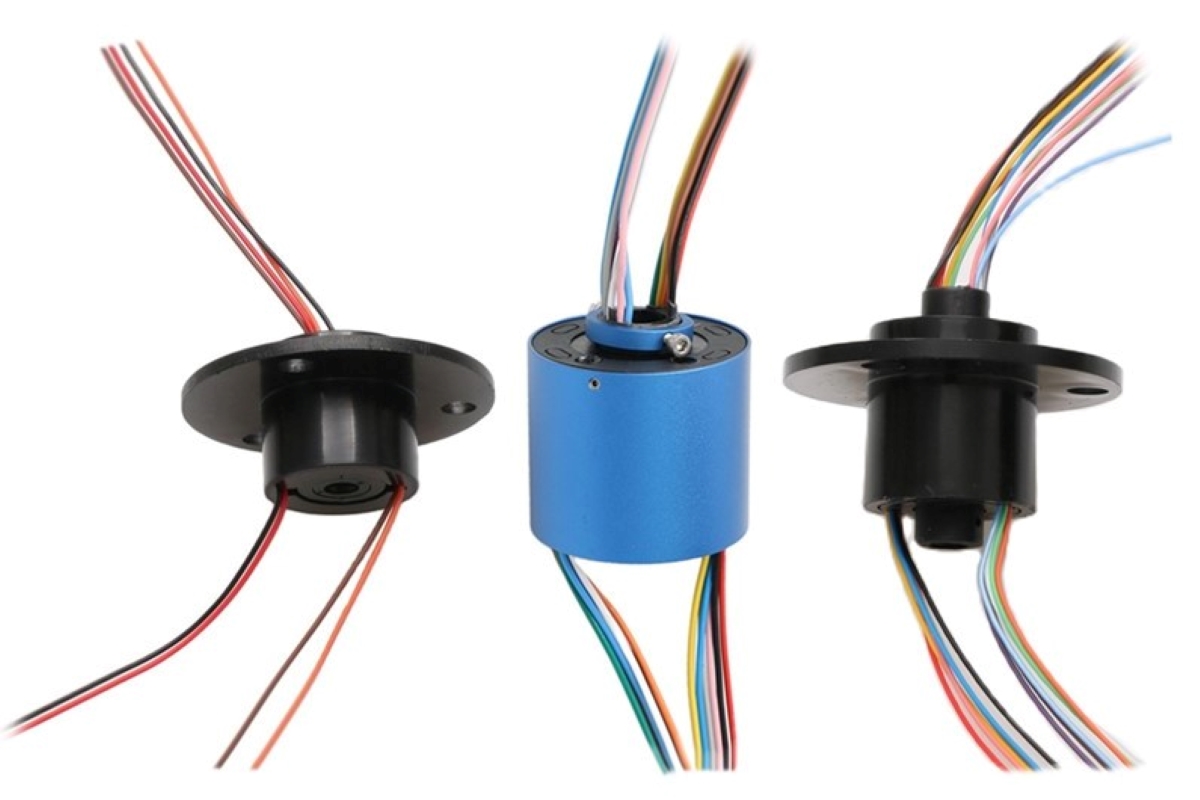
Rotating electrical connectors, also known as slip rings or rotary electrical connectors, are essential for applications such as wind turbines, cranes, robotics, and medical equipment. They allow for the continuous flow of power and data between stationary and rotating parts, eliminating the need for tangled wires or limitations due to rotational movement.
Whether you are a DIY enthusiast or an engineer seeking a customized solution, we will walk you through the key components, assembly process, and considerations for creating a reliable rotating electrical connector. Let’s dive in and explore the fascinating world of rotating electrical connectors!
Inside This Article
Materials and Tools Needed
Before you begin creating a rotating electrical connector, gather the necessary materials and tools. Here is a list of what you will need:
- Circular Connector: Choose a circular connector that suits your needs. It should have enough pins or contacts to accommodate the electrical connections you will be making.
- Rotating Disc: This will serve as the central rotating component of the connector. It should be made of a durable material like metal or plastic.
- Insulating Material: Select an insulating material that can prevent electrical contact between the rotating disc and the stationary part of the connector.
- Electrical Wires: You will need wires to make the electrical connections between the contacts on the circular connector and the rotating disc.
- Soldering Iron and Solder: These tools are essential for soldering the wires to the contacts and the rotating disc.
- Wire Strippers: Use wire strippers to remove the insulation from the ends of the electrical wires.
- Heatshrink Tubing: This tubing will provide insulation and protection to the soldered connections.
- Heat Gun or Lighter: Use a heat gun or a lighter to shrink the heatshrink tubing and secure the connections.
- Multimeter: A multimeter will help you test the continuity and integrity of the electrical connections.
- Electrical Tape or Insulating Sleeve: These materials can be used as an additional layer of insulation for added protection.
Once you have gathered all the necessary materials and tools, you can proceed with creating your rotating electrical connector. Make sure to follow the step-by-step instructions carefully to ensure a successful assembly.
Step-by-Step Instructions
Creating a rotating electrical connector may seem like a complex task, but by following these step-by-step instructions, you can successfully build one. Make sure you have all the necessary materials and tools on hand before you begin.
Here’s how to make a rotating electrical connector:
- Gather the Materials: You will need a sturdy base, a rotating mechanism such as a bearing or a slip ring, electrical connectors, wires, soldering iron, solder, and insulating materials. Ensure the connectors and wires are compatible with your specific application.
- Prepare the Base: Start by preparing the base for the rotating electrical connector. This might involve drilling holes to secure the rotating mechanism and routing channels for the wires to pass through. Make sure the base is sturdy and capable of supporting the weight and movement of the connector.
- Attach the Rotating Mechanism: Depending on the type of rotating mechanism you have chosen, carefully attach it to the base. If using a bearing, ensure it is securely mounted. If using a slip ring, follow the manufacturer’s instructions for installation.
- Connect the Electrical Connectors: Take the electrical connectors and attach them to the wires. Use a soldering iron and solder to create strong and reliable connections. Make sure to insulate any exposed wires or solder joints to prevent short circuits or electrical mishaps.
- Route the Wires: Carefully route the wires through the channels created on the base, ensuring they have enough slack to allow for rotation. It is crucial to prevent any strain or tension on the wires, as this could lead to damage or disruption during rotation.
- Secure the Wires: Use zip ties or cable clamps to secure the wires to the base. This helps to prevent them from becoming tangled or snagged during operation. Ensure the wires are organized and not obstructing the rotation of the electrical connector.
- Test the Connector: Once everything is in place, it’s time to test your rotating electrical connector. Connect it to the appropriate power source and check for proper rotation without any issues. Ensure all electrical connections are secure and no wires are touching each other, which could cause a short circuit.
- Troubleshooting: If you encounter any problems during the testing phase, carefully inspect the electrical connections, wiring, and rotation mechanism. Look for loose connections, damaged wires, or any signs of friction or misalignment. Address any issues accordingly for optimal performance.
Following these step-by-step instructions will help you create a rotating electrical connector that meets your specific needs. Remember to exercise caution, especially when working with electricity, and prioritize safety throughout the process.
Testing and Troubleshooting
After assembling your rotating electrical connector, it’s time to test it and troubleshoot any potential issues. Here are some important steps to follow:
1. Power Supply Check: Connect the rotating electrical connector to a power source, making sure the voltage and current are compatible. Use a multimeter to check if there is a proper supply of power. Ensure that the connector is securely connected to avoid any loose connections that could affect performance.
2. Rotation Test: Activate the rotating mechanism and observe if the connector rotates smoothly and continuously. Check if there are any abnormal noises or vibrations during rotation, as these could indicate potential issues such as misalignment or mechanical problems.
3. Electrical Continuity: Verify that there is a continuous flow of electrical signals through the connector. Use a continuity tester or a multimeter to check for any interruptions or open circuits. Inspect the conductor pins and contacts for any signs of damage or corrosion that could affect the signal transmission.
4. Signal Integrity Test: Connect the rotating electrical connector to the respective devices or circuits it is intended to interface with. Test the signal quality and integrity by sending and receiving data or power. Monitor for any dropouts, signal loss, or fluctuations that could indicate poor contact or insufficient insulation.
5. Heat Dissipation Check: During operation, monitor the temperature of the rotating connector. Excessive heat buildup could indicate poor conductivity or inadequate cooling. Ensure that the connector is designed to withstand the expected power load and has appropriate heat dissipation mechanisms in place.
6. Insulation Resistance Test: Measure the insulation resistance of the rotating electrical connector using a megohmmeter. This test helps identify any leakage current or insulation breakdown that could compromise the safety and reliability of the connector. Make sure the insulation resistance meets the required standards for your application.
If you encounter any issues during the testing phase, it’s essential to troubleshoot and identify the root cause promptly. Here are some troubleshooting tips:
– Check for loose connections or faulty wiring.
– Inspect the rotating mechanism for any obstructions or misalignment.
– Clean the connector contacts to ensure proper electrical contact.
– Verify that the power source is stable and meets the required specifications.
– Review the connector’s specifications and ensure compatibility with the devices or systems it is being connected to.
– Consult the manufacturer’s documentation or seek professional assistance if needed.
By following these testing and troubleshooting steps, you can ensure the functionality, safety, and reliability of your rotating electrical connector. Remember to always prioritize safety and consult experts if you are unsure about any aspect of the testing or troubleshooting process.
Conclusion
In conclusion, understanding the importance of a rotating electrical connector is crucial for various industries. Whether it is for transmitting power, signals, or data, these connectors play a vital role in ensuring seamless and reliable operations. By allowing continuous rotation without the risk of tangling or breaking wires, they enable efficient and uninterrupted performance in rotating machinery and equipment.
With advancements in technology, rotating electrical connectors have evolved to meet the demands of modern applications. From compact designs to enhanced durability and flexibility, they offer solutions that cater to diverse needs. Investing in high-quality connectors not only improves performance but also reduces maintenance and downtime, ultimately resulting in cost savings and improved productivity.
Whether you need a rotating electrical connector for robotics, wind turbines, medical equipment, or any other rotating machinery, it is essential to choose a reliable and reputable manufacturer. By selecting the right connector and properly maintaining it, you can ensure the smooth and efficient operation of your equipment, enhancing overall performance and longevity.
So, next time you encounter a rotating application, don’t forget the importance of a rotating electrical connector – an innovative solution that keeps the world spinning.
FAQs
1. What is a rotating electrical connector?
A rotating electrical connector, also known as a rotary electrical joint or a slip ring, is a device that allows the transmission of power, signals, or data between a stationary and a rotating structure. It provides a continuous electrical connection, even when the components are in motion.
2. What are the applications of rotating electrical connectors?
Rotating electrical connectors are widely used in various industries and applications. Some common applications include wind turbines, robotics, medical equipment, packaging machinery, cranes, electrical testing equipment, and many more. These connectors enable the transfer of power and signals in rotating systems, enabling seamless operation and data transmission.
3. How does a rotating electrical connector work?
A rotating electrical connector typically consists of two main components: a stationary part and a rotating part. The stationary part is connected to the power supply or data source, while the rotating part is connected to the rotating structure. The two parts are mechanically and electrically connected through brushes, rings, or other contact surfaces. This allows an uninterrupted transmission of electricity or signals while the components rotate.
4. What are the advantages of using rotating electrical connectors?
Rotating electrical connectors offer several advantages, including the ability to transmit power and signals without the need for physical cables that can become tangled or damaged. They also allow for rotational freedom, enabling continuous rotation without the worry of wire breakage. Additionally, they can accommodate a wide range of voltages, currents, and data rates, making them versatile for various applications.
5. Are there different types of rotating electrical connectors?
Yes, there are different types of rotating electrical connectors available, each designed to fulfill specific requirements. Some common types include slip rings, split rings, fiber optic rotary joints, coaxial rotary joints, and hybrid rotary joints that combine power and signal transmission. The choice of connector depends on factors such as the electrical requirements, data rates, environment, and the number of channels needed for transmission.