
Welcome to our article on the PATA IDE motherboard connector! If you’ve ever opened up your computer or built one from scratch, you may have come across this term. PATA (Parallel ATA), also known as IDE (Integrated Drive Electronics), is an older technology used to connect storage devices, such as hard drives and optical drives, to the motherboard. One common question that arises when discussing PATA IDE connectors is how many pins they have. In this article, we will answer that question and provide you with a deeper understanding of PATA IDE connectors, their purpose, and their compatibility. So, if you’re ready to dive into the world of computer hardware, let’s get started!
Inside This Article
Pin Configuration and Identification
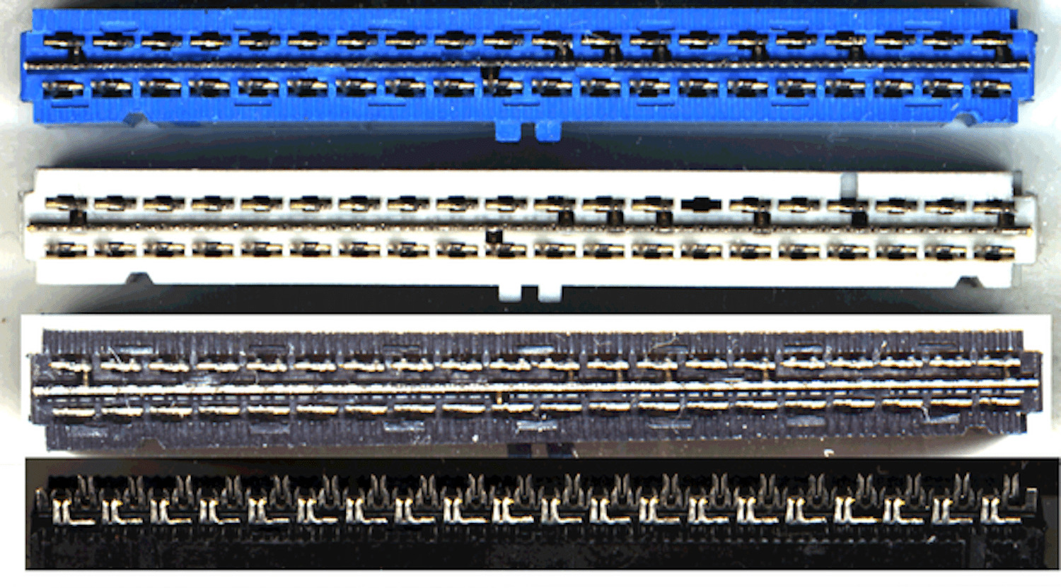
The pin configuration and identification of a PATA (Parallel ATA) IDE motherboard connector can vary depending on the specific motherboard manufacturer. However, most PATA IDE motherboards typically feature a 40-pin connector. This connector is responsible for connecting the motherboard to the PATA devices such as hard drives and optical drives.
To identify the pin configuration, it is essential to understand the labeling convention used on the connector itself. Each pin on the connector is labeled with a number, starting from pin 1 and going up to pin 40. The pins are arranged in two rows, with a total of 20 pins in each row.
Typically, the odd-numbered pins are on one row, while the even-numbered pins are on the other row. For example, pin 1 is often located on the left side of the connector, while pin 2 is on the right side, pin 3 on the left, and so on. This configuration helps ensure proper alignment when connecting the PATA cable to the motherboard.
The pin configuration and identification are crucial when connecting PATA devices to the motherboard. Each pin serves a specific purpose, allowing for the transmission of data and signals between the motherboard and the connected devices.
Signal Pins
In a PATA IDE motherboard connector, there are several signal pins that play a crucial role in the data transmission process. These pins are responsible for carrying the signals between the motherboard and the PATA IDE device, such as a hard drive or an optical drive.
Typically, a PATA IDE motherboard connector has a total of 40 pins. Out of these 40 pins, 39 pins are dedicated to transmitting various signals. Each signal pin serves a specific purpose and helps in the proper functioning of the PATA IDE device.
Some of the important signal pins found on a PATA IDE motherboard connector include:
- Address Pins: These pins help in determining the memory addresses for data transfer.
- Data Pins: These pins are responsible for carrying the actual data between the motherboard and the PATA IDE device.
- Control Pins: These pins are used for controlling the data transfer process and coordinating the flow of data.
- Interrupt Pins: These pins are used to handle interrupt requests during data transfer.
- Reset Pin: This pin is used to reset the PATA IDE device.
The exact configuration and arrangement of these signal pins can vary depending on the specific PATA IDE motherboard connector. It is important to refer to the motherboard’s documentation or consult the manufacturer to understand the pin configuration of a particular connector.
Understanding the signal pins on a PATA IDE motherboard connector is essential for troubleshooting any connection or data transfer issues. Properly aligning and connecting the pins ensures a stable and reliable connection between the motherboard and the PATA IDE device.
Ground Pins
Ground pins are an essential part of a PATA IDE motherboard connector. They play a crucial role in providing a reference voltage level and ensuring proper grounding for the signals transmitted through the connector.
The ground pins are responsible for creating a common ground connection between the motherboard and the connected devices. This helps in maintaining signal integrity and reducing electrical noise, ensuring reliable data transmission.
In a PATA IDE motherboard connector, there are usually multiple ground pins positioned strategically throughout the connector. These pins are typically labeled with the symbol “GND” or “ground” to indicate their purpose and function.
The number of ground pins may vary depending on the specific PATA IDE connector design. Typically, a PATA IDE motherboard connector has several ground pins, which are evenly distributed across the connector to provide an effective grounding system.
It is important to note that each ground pin is interconnected with the others, forming a network of ground connections. This helps to distribute the ground potential evenly and ensures that all connected devices have a common reference point for electrical signals.
Ground pins in a PATA IDE motherboard connector are usually connected directly to the ground plane on the motherboard. The ground plane is a conductive layer within the motherboard that acts as a common ground reference for all components and connectors.
By maintaining a solid and reliable ground connection, the ground pins in a PATA IDE motherboard connector contribute to the overall stability and performance of the system. They help to minimize the risk of electrical interference, improve signal integrity, and ensure the smooth operation of the connected devices.
Overall, the presence of multiple ground pins in a PATA IDE motherboard connector is essential for maintaining a robust electrical connection and ensuring optimal performance. These pins play a crucial role in creating a stable and reliable grounding system, which is vital for the proper functioning of the PATA IDE interface and the connected devices.
Power Pins
Power pins play a crucial role in providing the necessary electrical energy to the components connected to a PATA/IDE (Parallel Advanced Technology Attachment/Integrated Drive Electronics) motherboard connector. These pins ensure that the various devices, such as hard drives and optical drives, receive the power they need to function properly.
The power pins on a PATA/IDE motherboard connector are typically labeled as +5V, +12V, and Ground. The +5V pin supplies 5 volts of direct current (DC) power, while the +12V pin provides 12 volts of DC power. The Ground pin, as the name suggests, serves as the reference point for the electrical circuit and completes the power supply system.
It is important to note that the number of power pins on a PATA/IDE motherboard connector may vary depending on the specific motherboard model. However, the most common configuration consists of two +5V pins, two +12V pins, and two Ground pins.
The +5V pins are responsible for supplying power to the logic circuits, control circuits, and data transceivers. These pins ensure proper operation of the integrated circuits and data transfer between the motherboard and the connected devices.
The +12V pins, on the other hand, provide power to the motors in devices such as hard drives and optical drives. These motors require higher voltage to spin the disks and perform their mechanical functions effectively.
Proper power distribution is essential to avoid any potential damage to the components or motherboard. It is crucial to ensure that the correct voltage is supplied to the appropriate pins to prevent overloading or short circuits.
When connecting a PATA/IDE device to the motherboard, it is vital to align the power pins correctly. The connectors usually have a keying mechanism or a guide pin to ensure proper alignment, preventing any chances of reversed connections.
Conclusion
Overall, the PATA IDE motherboard connector is an essential component that plays a crucial role in connecting the storage devices to the motherboard. Its design and configuration play a significant role in determining the speed, capacity, and compatibility of the connected devices. The number of pins on a PATA IDE motherboard connector depends on the type of connector used. The most common types are the 40-pin and 80-pin connectors, which are used for different generations and speeds of PATA IDE interfaces.
Understanding the configuration and specifications of the PATA IDE motherboard connector is important for those looking to upgrade or troubleshoot their computer systems. By knowing the number of pins and the corresponding compatibility, users can ensure the seamless integration of storage devices and maximize the performance of their systems.
As technology continues to evolve, the PATA IDE interface has been largely replaced by more advanced and efficient options like SATA and NVMe. However, in older systems or specific applications, the PATA IDE motherboard connector remains a relevant and crucial component to consider. It is always recommended to consult the motherboard or product documentation for accurate pin and connector information specific to the system in question.
FAQs
1. How many pins are on a PATA IDE motherboard connector?
A PATA IDE (Parallel ATA Integrated Drive Electronics) motherboard connector typically has 40 pins. These pins are used to connect IDE devices such as hard drives and optical drives to the motherboard.
2. Can I use a PATA IDE connector to connect a SATA drive?
No, you cannot use a PATA IDE connector to connect a SATA (Serial ATA) drive. PATA and SATA are two different interfaces, and they are not compatible with each other. If you have a SATA drive, you will need to use a SATA connector on your motherboard or invest in a SATA-to-IDE adapter if your motherboard does not support SATA natively.
3. Are PATA IDE connectors still used in modern computers?
PATA IDE connectors are considered outdated and have been largely replaced by SATA connectors in modern computers. However, some older systems or niche applications may still utilize PATA IDE connectors. It’s important to check your motherboard’s specifications to determine if it supports PATA IDE connectors before purchasing any IDE devices.
4. How do I differentiate between a primary IDE connector and a secondary IDE connector?
On a motherboard that supports multiple IDE devices, there are usually two IDE connectors: one primary and one secondary. The primary IDE connector is designated for the primary IDE channel, often labeled as “IDE1” or “Primary” on the motherboard. The secondary IDE connector is designated for the secondary IDE channel, usually labeled as “IDE2” or “Secondary.” The primary IDE channel usually connects to the main hard drive, while the secondary IDE channel can be used for additional drives or devices.
5. Can I connect more than two IDE devices to a motherboard with only one IDE connector?
If your motherboard has only one IDE connector but you need to connect more than two IDE devices, you can use an IDE controller card or adapter. These devices can be installed in an available expansion slot on your motherboard and provide additional IDE connectors for connecting multiple IDE devices. This workaround allows you to expand the number of IDE devices you can connect to your system, beyond the limitations of the motherboard’s built-in IDE connector.