
In today’s digital age, staying connected is more important than ever. Whether it’s through our smartphones, tablets, or laptops, we rely on a myriad of electronic devices to keep us connected to the world around us. One crucial component of these devices is the system panel connector, which allows us to connect essential peripherals and accessories.
Connecting the system panel connector may seem daunting for those who are unfamiliar with the process. However, with a little guidance and knowledge, you’ll be able to do it with ease. In this article, we’ll provide you with a step-by-step guide on how to connect the system panel connector, ensuring that your device is ready to be fully utilized.
Whether you’re setting up a new device or troubleshooting an existing one, understanding how to connect the system panel connector is a valuable skill. So, let’s dive in and explore the world of system panel connectors together!
Inside This Article
- Understanding System Panel Connector
- Step 1: Identifying the System Panel Connector
- Step 2: Disconnecting the Existing Wires
- Step 3: Connecting the New Wires
- Step 4: Testing the Connection
- Conclusion
- FAQs
Understanding System Panel Connector
When it comes to building or troubleshooting a computer, understanding the system panel connector is crucial. The system panel connector, also known as the front panel header or front panel connector, is a set of pins on the motherboard that allows you to connect various buttons and indicators on the computer case.
The system panel connector plays a significant role in controlling power functions, such as turning the computer on and off, resetting the system, and indicating the presence of activity through LED lights. It is important to have a firm grasp of how this connector works to ensure the proper functionality of your computer’s front panel.
The system panel connector typically consists of a series of pins labeled with abbreviations such as PWR, RST, HDD LED, and PLED. Each pin has a specific function, and understanding these functions is essential for successfully connecting the wires from your computer case to the motherboard.
The PWR pin is responsible for powering the system on or off. When the power button on your computer case is pressed, it sends a signal to the PWR pin, telling the motherboard to initiate the boot-up process or shut the system down.
The RST pin is used to reset the computer. Pressing the reset button on your computer case sends a signal to the RST pin, causing the system to restart without turning it off completely.
The HDD LED pin connects to the hard disk drive activity indicator light on your computer case. When the hard drive is being accessed or is in use, this LED will flash, providing visual feedback on its activity.
The PLED pin connects to the power LED indicator on your computer case. This LED typically stays illuminated when the system is powered on, indicating that the power supply is functioning correctly.
Other pins may include speaker pins for connecting a speaker that emits beep codes during the system boot process, as well as USB and audio header pins for connecting front panel USB ports and audio jacks.
Understanding the layout of the system panel connector can vary depending on the motherboard manufacturer. It is essential to consult the motherboard manual or manufacturer’s website for the specific pin layout and labeling as they might differ slightly from one motherboard model to another.
Now that you have a basic understanding of the system panel connector, you can move on to the next steps of connecting and testing the wires. It is important to follow the motherboard manual’s instructions carefully to ensure proper connections and prevent any potential damage to your system.
Step 1: Identifying the System Panel Connector
The system panel connector, also known as the front panel header or system header, is an essential component in connecting various buttons, LEDs, and other control devices on your computer’s front panel. It allows you to interact with your computer by providing access to power buttons, reset buttons, audio jacks, USB ports, and other essential features.
To begin the process of connecting the system panel connector, you first need to identify its location on your motherboard. The exact location may vary depending on the motherboard manufacturer and model, but it is commonly found near the bottom edge of the motherboard, close to where the front panel of your computer’s case connects.
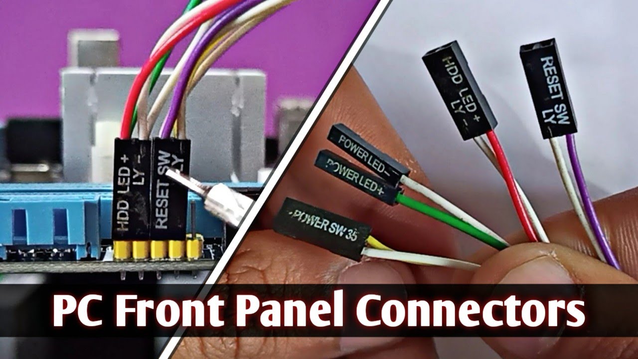
You can identify the system panel connector by looking for a block of pins or a set of labeled headers on the motherboard. These pins or headers are usually labeled with abbreviations such as PWR_SW (power switch), RST_SW (reset switch), HDD_LED (hard drive activity LED), PWR_LED (power LED), and so on.
If you are having trouble locating the system panel connector on your motherboard, don’t worry. You can refer to the motherboard’s manual or visit the manufacturer’s website to download the manual for your specific model. The manual will provide detailed information on the location and pin layout of the system panel connector.
Once you have identified the system panel connector, it’s time to move on to the next step: disconnecting the existing wires. This will ensure a clean and organized setup for connecting the new wires.
Step 2: Disconnecting the Existing Wires
Before you can connect the new wires to the system panel connector, you’ll need to disconnect the existing wires. This step is crucial to ensure a clean and error-free installation. Follow these instructions to disconnect the existing wires:
1. Begin by identifying the wires connected to the system panel connector. Carefully inspect the connector to locate the wires that need to be disconnected.
2. Once you have identified the wires, gently grip the plastic connector housing near the base of the wire. Be careful not to pull on the wire itself, as this could damage the connection.
3. Firmly but gently pull the connector straight out of the system panel. If the connector feels stuck, check for any locks or clips that may be holding it in place. Release the locks or clips before attempting to pull the connector out.
4. As you disconnect each wire, make sure to keep track of its location and orientation. Taking a picture or labeling the wires can be helpful for reinstallation. This will ensure that you can easily reconnect the wires in the correct positions later on.
5. Repeat this process for each wire connected to the system panel connector. Take your time and be patient, as it’s important not to rush and risk damaging the wires or the panel connector.
By following these steps, you can safely and effectively disconnect the existing wires from the system panel connector. Once the wires are disconnected, you can proceed to the next step of connecting the new wires.
Step 3: Connecting the New Wires
Now that you have identified and disconnected the existing wires, it’s time to connect the new wires in the system panel connector. Follow these easy steps to ensure a successful connection:
1. Refer to the motherboard manual: Before proceeding, it’s important to consult the motherboard manual for the specific wiring diagram related to the system panel connector. The manual will provide detailed instructions on how to properly connect the wires.
2. Organize the new wires: Take a moment to organize the new wires before connecting them. Untangle and straighten the wires, making it easier to work with during the installation process. Ensure you have the necessary tools, such as tweezers or needle-nose pliers, to handle the delicate wires.
3. Match the wires: Carefully examine the labels or color-coding on the new wires and match them with the corresponding pins on the system panel connector. Each wire will have designated pins for power LED, power switch, reset switch, HDD LED, and other components. Refer to the motherboard manual for the exact pinout configuration.
4. Connect the wires: With the labels or color-coding in mind, gently insert each wire into the corresponding pin slot on the system panel connector. Ensure that the wire is securely inserted and properly aligned with the pins.
5. Double-check the connections: Once all the wires are connected, take a moment to double-check the connections. Ensure that each wire is securely attached and properly aligned. Any loose connections may result in functionality issues or improper functioning of the system panel components.
6. Reassemble the computer: After successfully connecting the new wires, it’s time to reassemble your computer. Carefully place the motherboard back into the case and secure it with the screws. Reconnect any other components that were disconnected during the process, such as the power supply cables and data cables.
7. Power on the computer: Finally, power on your computer to test the system panel connector connections. Check if the power LED, power switch, reset switch, and HDD LED are functioning properly. If any issues arise, double-check the wiring connections and consult the motherboard manual.
By following these steps, you’ll be able to successfully connect the new wires to the system panel connector and ensure your computer functions seamlessly.
Step 4: Testing the Connection
Once you have successfully connected the system panel connector to the motherboard and front panel, it is time to test the connection to ensure everything is working properly. Testing the connection will ensure that all the buttons and indicators on the front panel are functioning as intended.
To test the connection, follow these steps:
- Power On the System: Start by powering on the system. Press the power button on the front panel of your computer case.
- Observe Lights and Indicators: Pay attention to any lights or indicators on the front panel. Check if the power indicator light turns on and remains steady.
- Test the Reset Button: Press the reset button on the front panel. It should initiate a system restart. Observe if the system restarts and if the reset button resumes its normal position when released.
- Check Other Buttons: Test the functionality of other buttons on the front panel, such as the power button, HDD LED, and any other buttons or indicators present. Press each button and observe if it performs the expected action.
- Ensure Proper Wiring: While testing, keep an eye on the wiring connections to ensure they remain intact and secure. If any wires come loose or disconnect during testing, you may need to revisit the previous steps and reassemble the system panel connector.
If you encounter any issues during testing, double-check the wiring connections and make sure they are firmly in place. If the problem persists, consult the motherboard or computer case manual for troubleshooting instructions. It’s also a good idea to reach out to the manufacturer’s support for assistance.
Testing the connection is an essential step to ensure that your system panel connector is properly installed and functioning. By following these steps and troubleshooting any issues that may arise, you can enjoy a fully functional front panel on your computer case.
Conclusion
The process of connecting the system panel connector may seem daunting at first, but with the right guidance, it becomes an effortless task. By understanding the different pins and connectors on the motherboard, you can easily connect your power button, reset button, and LED indicators.
Remember to carefully align the pins with their respective labels on the motherboard, ensuring a secure and reliable connection. Take your time and double-check your work to avoid any potential issues.
With this knowledge and the step-by-step guide provided, you can confidently connect your system panel connector and embark on your journey to building the perfect computer system.
Now that you have mastered this skill, you are one step closer to assembling your dream computer. Happy building!
FAQs
1. How do I connect the system panel connector?
Connecting the system panel connector is a crucial step in building or upgrading your computer. To do so, follow these steps:
- Refer to your motherboard’s manual to locate the system panel connector pins.
- Identify the individual wires from your computer case’s front panel, which typically include power switch, reset switch, power LED, and HDD LED.
- Match the corresponding wires to their respective pins on the system panel connector. Usually, the connectors or pins are labeled on the motherboard.
- Gently insert each wire into its proper slot on the connector. Be sure to align the polarity correctly.
- Once all the wires are connected, double-check the connections to ensure they are secure.
2. What happens if I connect the system panel connector incorrectly?
Connecting the system panel connector incorrectly can lead to various issues. Some common problems include:
- The power button not working or being unresponsive
- The reset button not functioning
- The power LED not illuminating
- The HDD LED not showing activity
- The computer not starting or booting up
To avoid these issues, carefully refer to your motherboard’s manual and double-check the connections to ensure everything is properly connected.
3. Can I connect the system panel connector backward?
No, you should not connect the system panel connector backward. Most modern motherboards have polarity protection, which means the connector can only be inserted one way. Trying to force it in the wrong direction may damage the pins or the connector itself. Always make sure to align the pins and connectors correctly before inserting them.
4. Are all system panel connectors the same?
No, system panel connectors can vary depending on the motherboard and computer case manufacturer. While the basic functions are similar (power switch, reset switch, power LED, HDD LED), the pin layouts and configurations may differ. It’s essential to consult your motherboard’s manual and the case manufacturer’s documentation for the correct pin assignments and connections.
5. Can I connect the system panel connector without the motherboard manual?
While it’s always best to have the motherboard manual for reference, you can still connect the system panel connector without it. Here’s what you can do:
- Check the motherboard manufacturer’s website for a digital copy of the manual, which is often available for download.
- Search online forums or communities where users may have shared the pin configurations for your specific motherboard model.
- Observe the labelings or markings on the motherboard itself, as some manufacturers include pin assignments directly on the board.
- Consult the computer case manual or documentation, as it may provide some guidance on connecting the system panel connector.
However, for the most accurate and safe connection, it is highly recommended to obtain the motherboard manual to ensure the correct pin assignments and prevent any potential damage.